I’ve been using Civil 3D for a little while now and wanted to create a short blog with a few tips I found along the way to create a corridor (road design).
1. So first thing’s first, you will need a surface (existing ground). This can be created from many many different types of survey. Mine was created using a DWG file with points and strings tidied up and cleaned to give a nice lean existing ground survey.
2. You will then need to create a horizontal alignment. This can be done using a 2D road design overlaid and x-referenced in.
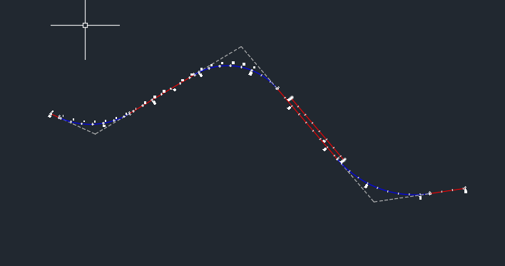
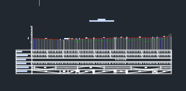
3. Once you have the horizontal alignment you will need to create a profile so that you can then create a vertical alignment.
4. The horizontal and the vertical alignments need to match in length exactly or else the corridor will not be created properly.
5. Once both alignments are created you need to create an assembly. This is the equivalent of a road section with surface depths, sub-earth depth, kerbing, banking, etc.

6. Once your assembly is built you need to apply this to your alignment using the corridor function and hey presto, you will have a corridor and basic road design.
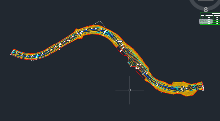
This is a simplified step by step of creating a corridor. There are many things to consider along the way, but hopefully this overview will help those who are starting to understand the processes required to create more complicated designs.
For more information on this blog post or if you have any other questions/requirements, please complete the below form:
Related Links
AutoCAD Civil 3D – Autodesk Platinum Partner | Man and Machine
Civil 3D Training Courses – Autodesk Authorised | Man and Machine